Interfacing Jablotron 100 without cloud
- Oct 17, 2020

Interfacing Jablotron systems to PC/domotica without Cloud
For our new office we wanted to have both an electronic security system with PIR motion detectors, glass break detectors etc as well as a video surveillance system, both indoors and outdoors.
For the video surveillance system we have a range security camera's that offer good picture quality at night, combined with the Blue Iris (BI) video surveillance software that runs on a Window PC.
Although the security cameras themselves as well as the BI software offer motion detection features based on the video image, video based motion detection is nowhere near as reliable as a Passive InfraRed motion detector or PIR. In particular, video based motion detection is prone to false positives, especially outdoors but also indoors, as they can be triggered by shadows, moving trees, headlights from cars etc. Getting no false positives with no missed real events is essentially impossible under most circumstances, except perhaps indoors in a room with no windows and guaranteed constant lighting conditions.
As such, trying to use a video surveillance system as an alarm system is not an option. In our opinion, security is achieved by layering which in our case will consist of the following:
- 1. Physical
Solid doors, windows and window frames, quality locks and other measure that increase the time it takes for a burglar to gain entrance such as window security foil. If it takes too long for them to get in you have effectively foiled their plans (pun intended). - 2. Procedures (and following them)
The best doors and locks are of no use whatsoever if they are left open so make sure those doors get locked - 3. Alarm system
An alarm system can act as a deterrent and also reduce the time burglars have to look for valuables. - 4. Security cameras
Only after all of the above have been taken care of is there a truly practical use for security cameras (an exception being 24/7 actively monitored video surveillance). In our case the main job for the video surveillance system is for verification of alarm notifications received from the alarm system.
For our new office we have chosen to install a Jablotron JA-103 based alarm system. One requirement was that we wanted to have the Jablotron 100 alarm system serve as a trigger for our Blue Iris based security camera system. Specifically, we wanted Blue Iris to record and send video of motion or other events detected by the alarm system.
The reason for that is for alarm verfication, which we found important for a number of reasons:
- Our office is in the middle of a residential area. Any false alarms with the indoor and outdoor sirens going off at night are unacceptable.
- With live video verification of an ongoing burglary we can actually call the emergency number 112. If the operator can be told that the burglars are still inside the premises as witnessed through a live video stream, the chance of getting some cops dispatched immediately is significantly increased.
- Apart from an outdoor siren we also have some very loud and obnoxiously sounding indoor sirens and we wanted to make sure that these are never triggered while there are still people inside. So both the outdoor and indoor sirens are triggered manually remotely after video verification.
An additional requirement that we had was that the solution should be completely cloud-free: no connection or dependency on any manufacturer's Internet 'cloud' servers or smartphone apps whatsoever.
Some way had to be found therefore to forward alarm events from the Jablotron system to BI. It's possible to have the Jablotron system send an email when an alarm event occurs, however that only works through the Jablotron cloud servers so that option was dismissed.
It turned out that the only way to accomplish this was by using the facilities in the Jablotron system to send alarm and other notifications to an Alarm Response Center or ARC. The Jablotron F-Link software can be used to setup such links under (System) Settings in the ARC tab.
The physical Ethernet network connection of the JA-103K can be found on the main PCB (printed circuit board) in the control panel as shown below:
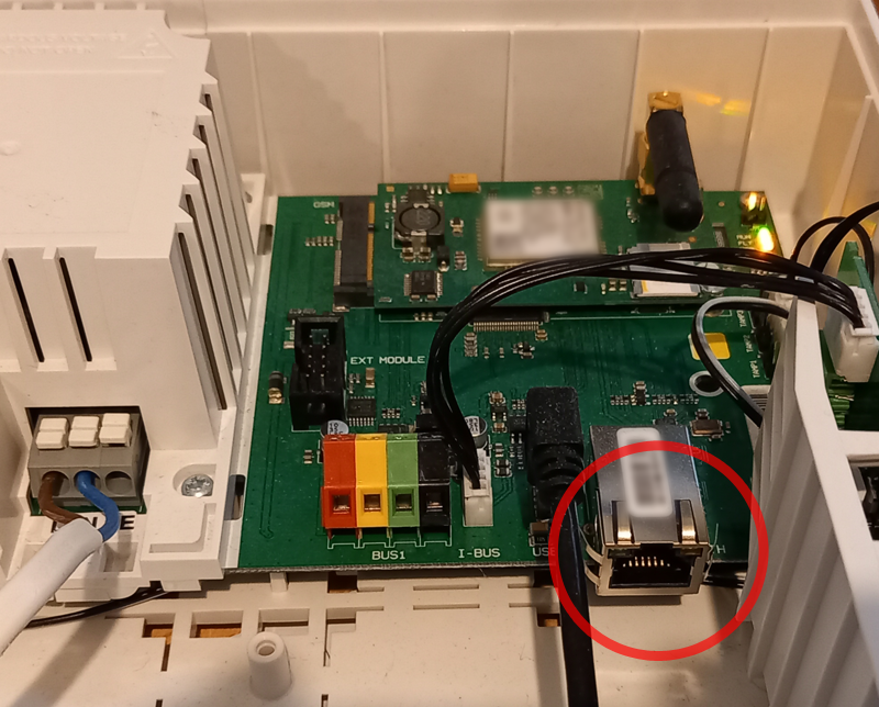
Figure 1: RJ-45 Ethernet LAN connector inside JA-103K Control Panel
So what we needed was some software that would play the role of an ARC so that it would be notified by the Jablotron system if something happened and would then forward the information to BI to trigger sending a notification with a video recording.
Jablotron Communication Protocol
A number of different communication protocols are supported by the Jablotron system for connecting to ARCs: JabloIP, JabloSMS, CID and IP SIA. Of these, the JabloIP protocol is proprietary and not publicly documented and it's probably used exclusively Jablotron for their own Cloud services.
Of the others, IP SIA seemed like the simplest to implement and we were able to find the most documentation on how this works, with seemingly all the required details to implement this.
As it turns out there are some computer programs that appear to support handling SIA messages to some degree, however those did not meet our specific requirements which included wanting the software to run on a Windows PC (the same one that hosts the BI software) and no easy way to map SIA alarm notifications from specific detectors (PIR sensors such as as tje JA-181PB) to a specific camera. Also, it seemed like a fun little project to work on.
We therefore decided to embark on writing a piece of software that satisfies our specific needs. Initially, we planned to keep it really simple by creating a simple console program (ie. a command line program with no graphical user interface) and that is how it started, but as we progressed this evolved into something quite more elaborate as you will see.
The IP SIA protocol is a modernized version of the original SIA protocol which was used for example over analog telephone lines . IP SIA used standard Internet protocol (IP) communication so as a long time Windows programmer I decided to give it a go and see if I could implement a SIA server.
With IP SIA, short messages are sent to the ARC which contain information about the type of event (alarm, burglary, panic, medical) through defined SIA event codes, as well as information about the device that triggered the event (PIR, glassbreak etc).
According to the SIA documentation, these messages can be transmitted over UDP or TCP network protocol but the JA-103K only implments UDP so that is what we implemented.
First we had to setup the JA-103K to send out SIA message in the first place. This is done using the F-Link software in (System) Settings under the ARC tab (ARC stands for Alarm Reponse Center):
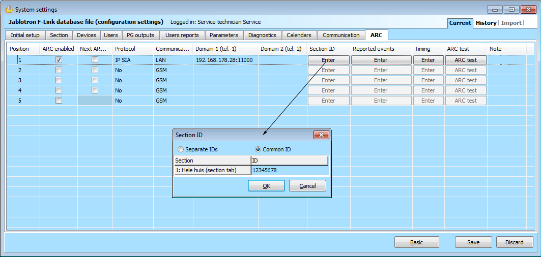
Figure 2: F-Link ARC settings
- Check ARC enabled
- Select Protocol IP SIA
- Select Communicator LAN
- In Domain enter the IP address of the remote system (a Windows PC in our case) that the SIA messages should be sent to and the port number on which the remote system will be listening in the common format IP address:port, eg. 192.168.178.28:11000
- Click the Enter button in column Section ID and enter the ID to be associated with the messages that are sent. You can send either one common ID for every section or you can assign different IDs to different sections.
This actually had us stumped for a while as initially we were not receiving SIA messages from the JA-103K on our PC, in fact we received not a single UPD package as evidenced by sniffing the net work traffic using Wireshark. Thanks to Jablotron support we found out that this was due to not setting an ID. Once the ID was set, we started receiving packages and could start our work on decoding these
SIA protocol messages are very simple and short and have the following format:
<LF> <CRC> <0LLL> <"ID"> <Sequence#!segment#|> <RReceiver#> <LLine#> […data…]<timestamp> <CR>
Below is an example of a message coming from the JA-103K (shown in C# string format):
"\n?007c\"SIA-DCS\"0002L0#12345678[#12345678|Nri01^Hele huis (section tab)^/RX921^ARC 1^][IManual test][H18:35:56]_18:35:57,08-01-2020\r"
If we split the message from the JA-103K according to what the SIA standard describes we get the following:
|
SIA documentation |
Actual message content |
|
<LF> |
\n |
|
<CRC> |
?00 (actually two raw bytes 0x0f 0xb5) |
|
<0LLL> |
7c |
|
<"ID"> |
\"SIA-DCS\" |
|
<Sequence#!segment#|> |
0002 |
|
<RReceiver#> |
??????? (field is missing in the data received) |
|
<LLine#> |
L0 |
|
????????? |
#12345678 |
|
[…data…] |
[#12345678|Nri01^Hele huis (section tab)^/RX921^ARC 1^] |
|
[…data…] |
[IManual test] |
|
[…data…] |
[H18:35:56] |
|
<timestamp> |
_18:35:57,08-01-2020 |
|
<CR> |
\r |
The message sent by the JA-103K appears to deviate from what the standard says, at least according to the documentation that we have. Either our documentation is outdated or incorrect or Jablotron have made some proprietary changes in their implementation.
The differences are the following:
- The CRC field (Cyclic Redundancy Checksum) is sent as two raw bytes by the JA-103K. According to the SIA documentation that we have, the CRC is supposed to be in human-readable hex-ascii representation:
7.1.2 <CRC> Cyclic Redundancy Check
This is the checksum associated with the message and used for error detection. The actual CRC field
is a 4-byte field representing a 16 bit CRC value and presented in ACSII encoded hexadecimal
notation, also known as Hex-ASCII. (For a detailed description of Cyclic Redundancy Check
calculation, see Appendix B.)
So in this case that would be 4 bytes which would be represented as a 4 character ASCII string: "0fb5". The JA-103K on the other hand sends it as 2 raw bytes. We also need to use this 2 raw bytes format in our ACK messages in order for the JA-103K to accept them (more on that later). - The mandatory <RReceiver#> field seems to be missing. Possibly the order of <RReceiver#> and <LLine#> is reversed? But then the literal "R" is missing which should be there for that field.
The #12345678 in this message is in fact the (common) Section ID that we have entered in F-Link in the ARC tab, so it would appear that the JA-1038K is sending the Section ID as the <RReceiver#> field but with Receive and Line in reverse order (compared to what the SIA documentation says) and without the "R" prefix.
When a SIA event message such as this is received, the receiver (normally an ARC monitoring the alarm system) is supposed to send back an ACK message with a similar format but omitting all the [data] bits. The above deviations from the standard made it difficult at first to get the JA-103K to accept our ACK messages which resulted in the JA-103K repeating the messages several times and ultimately reporting a failure to communicate with the ARC. New events would get delayed as a result but fortunately we finally managed to construct an ACK message that was accepted by the JA-103K.
Splitting and decoding the SIA message is fairly trivial but by this time we had developed some very specific ideas about how we would want to design a nice GUI (Graphical User Interface) a more general purpose which would allow us to easily map SIA events to other actions.
Below we will explain what the software does, how it works and how it can be used.
The main window display a number of tabs as shown below:
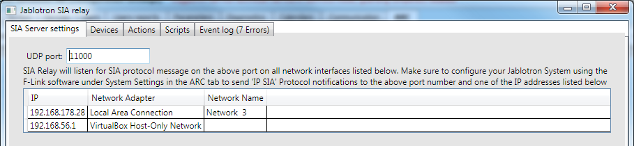
Figure 3: SIA Server settings tab
The firs tab SIA Server settings (shown above), simply allows you to define the UPD port to which the software listens for SIA messages. This must match the port part in the F-Link Settings discussed previously. It also lists the network adapters found on the PC. The current implementation of the software simply listens for SIA message on each adapter found. Note that at least one of the network connections of the PC must be in the same 'subnet' as the Jablotron control panel.
The second tab Devices is shown below:
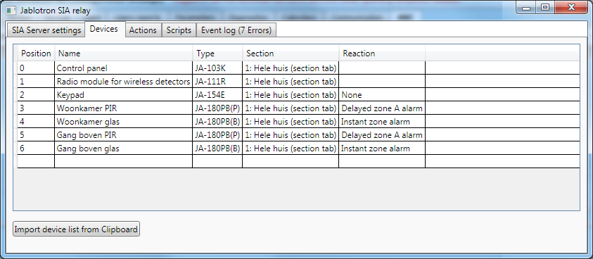
Figure 4: Devices tab
This tells the software which devices exist in the alarm system and enables. To populate the list you can simply open the Devices tab in F-Link's Settings window, right-click and Select All followed by Ctrl+C on the keyboard to copy the list onto the Windows Clipboard. We can then simply click the Import device list from Clipboard button to import the whole list into the software.
The next tab is where, literally, most of the action happens:
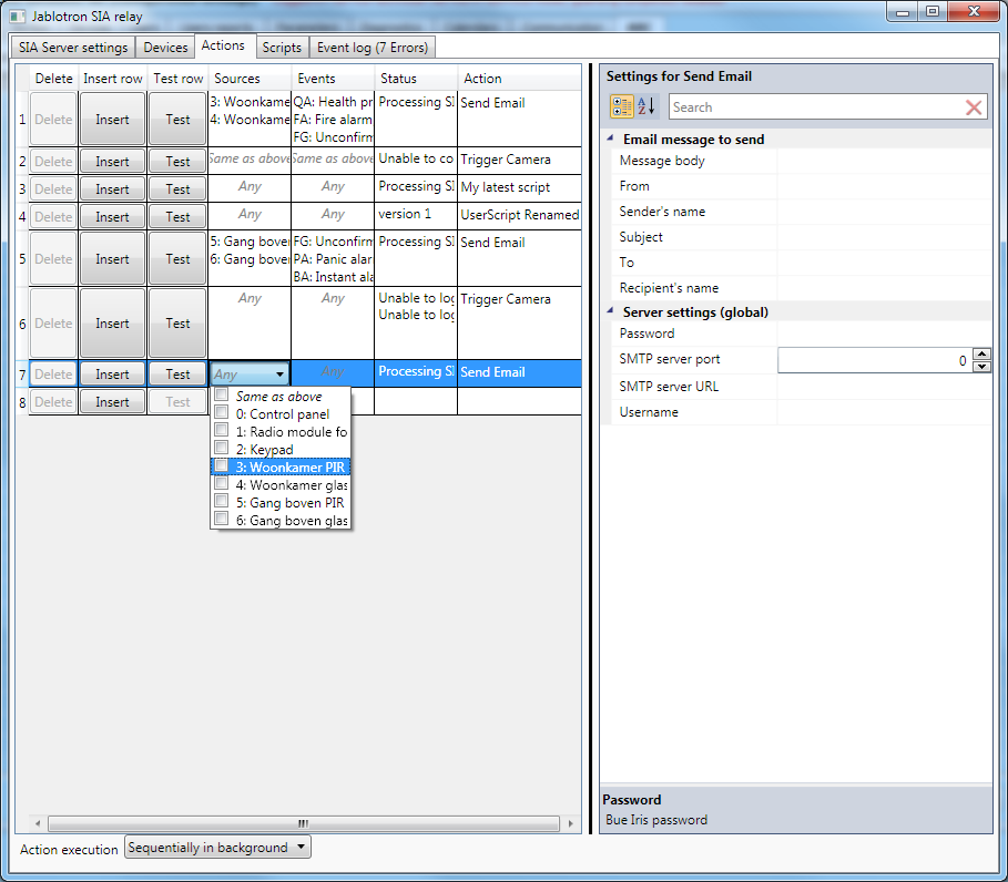
Figure 5: Action tab
Each row is a rule or mapping that maps a combination of Source device(s) and SIA Event type to a specific Action to be taken when that combination occurs.
The Delete, Insert and Test columns are self-explanatory. Below we will go over the other columns:
- Sources
Here you can select one or more Source devices such as specific PIRs, Glassbreak and other types of detectors. If a SIA messages comes in with a Source Device that is not checked in this list, the message is ignored by this row.
If you need another row that responds to the same Source, simply check Same as above. - Events
Here you can select one or more SIA Events, such as Burglar Alarm (SIA code BA), Tamper Alarm (TA) etc. Again if a SIA messages comes in with an Event that is not checked, the message is ignored by this row.
And yet again, if you need another row that responds to the same Event, simply check Same as above. - The Status column displays information about this row's selected Action
- Action
If the received SIA message's SIA event and Device are checked in the Sources and Events columns, the Action selected here is executed. To select an Action, simply select it from the dropdownlist and set it's properties using the Property editor on the right.
If you want multiple Actions to be fired for a certain combination of Source(s) and Event(s) you can simply add one or more rows and check Same as above for both the Source and Event column.
There are two pre-defined Action types: Trigger Camera and Send Email:
- Trigger Camera
This allows triggering a camera on a Blue Iris video surveillance server. What happens next is defined inside Blue Iris but in our case it causes BI to send a Push notification to an smartphone to allow verification of the alarm and in addition an email which includes both a snapshot and a short video fragment as an attachment.
There are a number of properties to be set for this Action. Global settings are the IP address, port number, username and password of the BI server.
For each row you can select up to 4 camera's (or camera groups) to be triggered
- Send Email
This allows sending an email through an SMTP mail server.
Global settings are the IP address, port number, username and password for the SMTP server. In a corporate environment the SMTP server might be managed by your company's IT department. Otherwise you can obtain details regarding the SMTP server you can use from your ISP. If you have a GMail account you can also use the GMail SMTP server.
For each Row/Action individually you can define a Subject, Message body, From email address, Sender's name, To email address and Recipient's name. For the Subject and Message body you can insert placeholders [Event] and [Source] which will be replaced by the actual Event and Source that triggered the Action.
The Action execution selection control allows changing how events are executed in reponse to an incoming SIA message:
- Sequentially
Each Action to be executed will run to completion in the main thread before the next Action is started. If the Actions take a long time to complete this will cause the user interface to become unresponsive so this not recommended. It might help when debugging in some cases. - Sequentially in background
Each Action to be executed will run to completion in a backgroudn thread before the next Action is started. The advantage of this is that the order of the sequence of events in the Event log remains the same and is easy to follow. - Parallel in background
All actions are exected in parallel in background ('worker') threads. In principle the best setting but it can make it more difficult to follow what is happening in the Event log because things will not be done in order.
You are not limited to just sending emails or triggering a camera in a Blue Iris server. You can also define your own Actions through C# scripting which is the done in the next tab, Scripts:
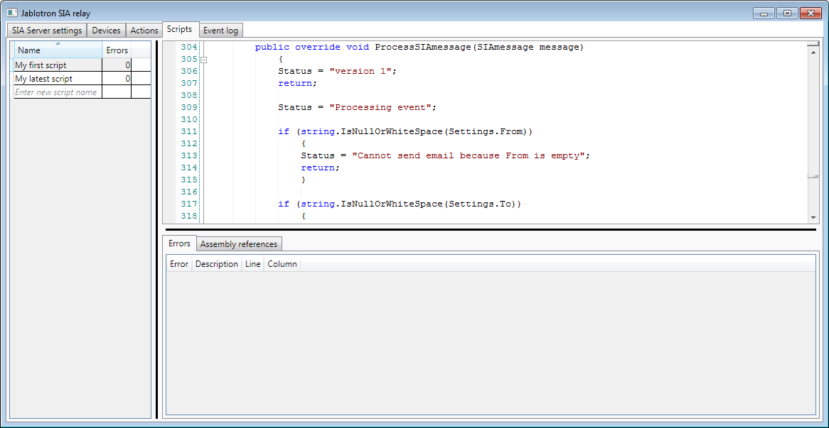
Figure 6: Scripts tab
We won't be covering the scripting in detail but for someone familiar with programming in C# you implementing Actions should be very straightforward: Simply define a new class derived from either the ISIAServerPlugin interface (or the SIAServerPluginBase if you want to save yourself some work by using some default implementations for some methods) and implement a number of methods such as ProcessSIAMessage, SaveData, RestoreData and an embedded SettingsClass whose properties will be shown and can be edited in the Actions tab.
What you do in ProcessSIAMessage is entirely up to the user. Implementing SaveData and RestoreData can be done in a trivial manner by simply calling the built-in JSON functionality and the SettingsClass is also entirely up to the user. If necessary you can add references to other .NET assemblies so really anything and everything is possible.
The last tab is the Event log which provides details about SIA messages received, which Actions have been executed as a result and what the outcome was of each Action:
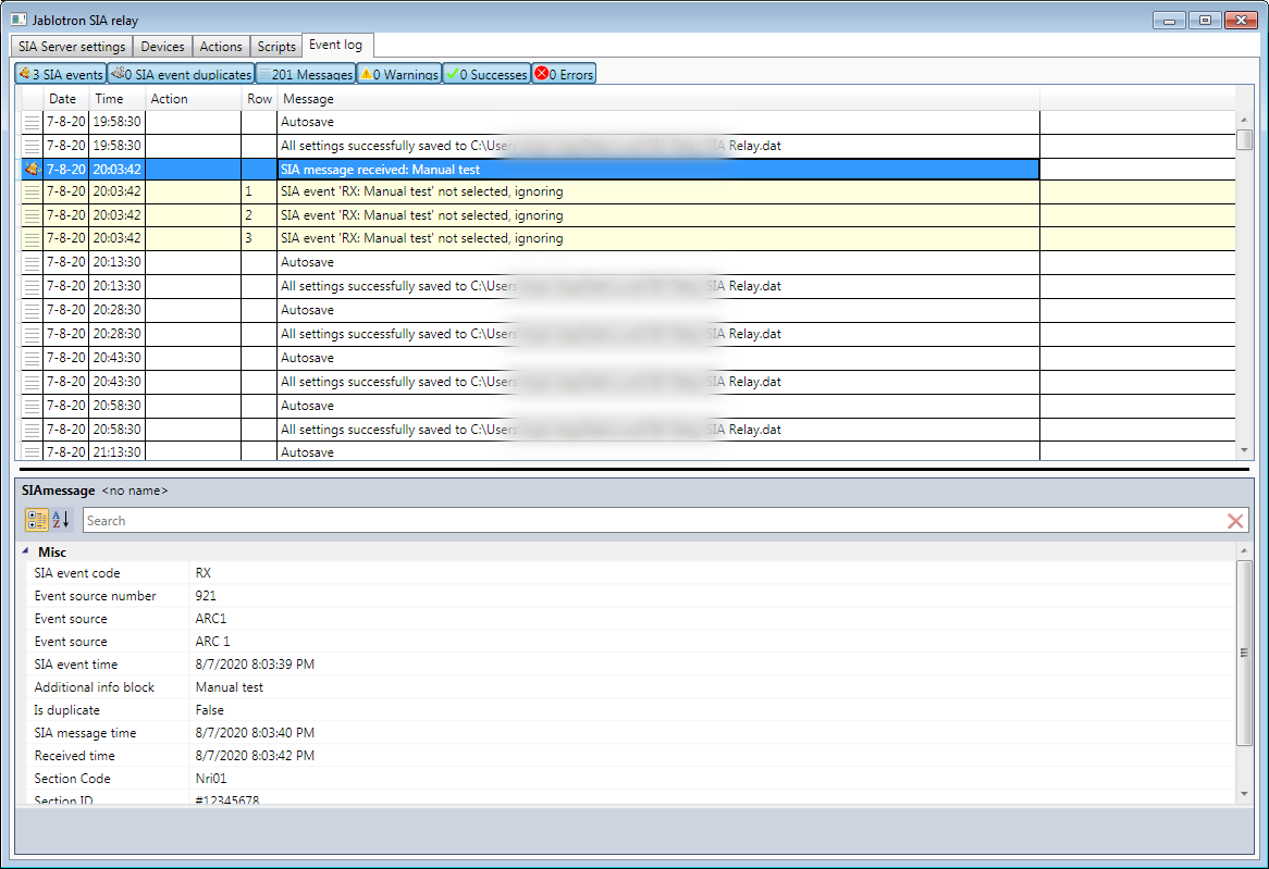
Figure 7: Event log tab
Selecting an entry in the event log will caused that and all associated log entries to be highlighted, making it easy to follow the sequence of events, which is especially helpful of Action execution is set to Parallel in background.
If you right-click on the event log, a Popup menu will appear with two choices:
- Clear log
- Location in Actions tab
Selecting this will cause a switch to the Actions tab with the Row/Action corresponding to this log entry selected.
If you remember, this whole exercise started out from a desire to verify an alarm before sounding an external siren such as the JA-163A to prevent disturbing our neighbors in the residential area we're located in. The JA-103K itself does not provide such functionality. It's possible to disable the Siren so that it does not sound when an Alarm is triggered and to use a PG output to trigger the JA-163A to make some loud beeping noises but it's not quite the same as the regular alarm sound which draws much more attention. In addition, the light of the JA-103K doesn't flash if you trigger it this way.
So we decided to do a little modification to the JA-163A to give it the functionality we desired.
WARNING: Do not attempt to open or modify your JA-163A or any other electronic apparatus. There could be lethal voltages inside and any modifications you make will certainly void your warranty. The following is form informational and entertainment purposes only and is in no way a solicitation to attempt any of the modifications described.
We happen to be electrical engineers ourselves so we decided to take a look at inside the JA-136A to see what we could do.
The inside of the JA-163A consists of three main parts:
- PCB
- Lithium battery (3.6V, non-rechargeable)
- Two speakers
The PCB with the wireless receiver, microcontroller and amplifier circuits is connected by a single lead with 2 cores to the speakers which are connected in parallel. If we could disconnect and connect this connection at will we could easily disable the speaker and only enable the connection to the speakers after verifying that there is indeed an alarm situation that would benefit from (literally) sounding the alarm. Even with the speakers disconnected, the JA-163A does start flashing if an alarm occurs by the way.
One way to achieve our goal might have been to modify the firmware (software) of the JA-163A which uses a well-known microcontroller but that would probably have been a lot of work. As it happens there is a switchable relay available from Jablotron, the JA-151N, which can close or open its relay based on a PG output, which in turn can be enabled and disabled by sending an SMS message to the JA-103K control panel. This seemed perfect for our purpose and luckily the JA-151N is small enough to fit inside the JA-163A housing along with a battery housing suitable for 3 AA size Lithium batteries, providing 3x3.6=10.8V which is well within the acceptable voltage range for the JA-151N.
Basically all we had to do is cut the wire from the PCB to the speakers, re-solder one of the cores so that it still goes straight from the PCB to the speakers and connect the other core to the COM (common) screw connection of the relay on the JA-151N. Then we connected the other wire coming from the speakers to the NO (Normally Open).
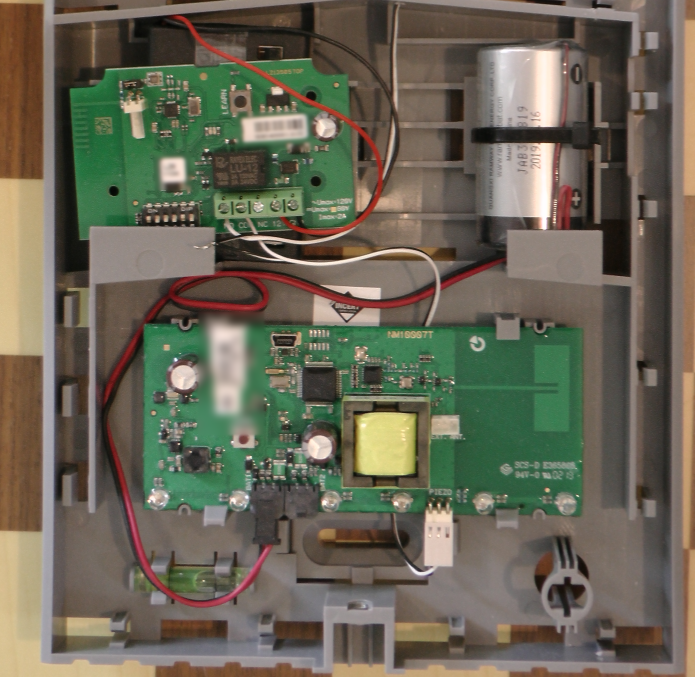
Figure 8: Original trivial modification to enable/disable the audible part of the siren
With the relay not activated (in principle the default condition, there is no complete circuit connection between the PCB and the speakers and when the relay is activated the circuit is completed and if the JA-163A is in an alarm state it the audible part of the alarm signal can be heard.
To allow control of the JA-151N remotely by SMS text message, some settings must be made in the PG output tab of Settings:
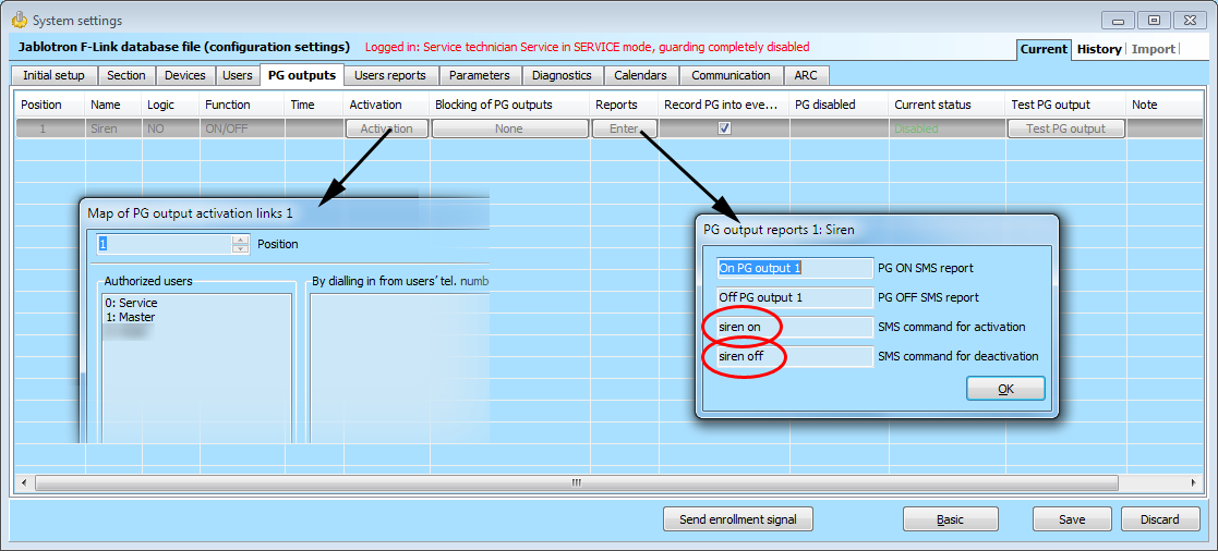
FIgure 9: Setting up the siren enable/disable PG output
The Logic must be set to NO (Normally Open) and the Function to ON/OFF. The user that will be sending the SMS command to activate the siren must be authorized to do so (Activation button). In the Reports column click on Enter to set the SMS commands for activation and deactivation of the siren, for example siren on and siren off respectively.
With these settings, enabling the audible siren part of the JA_163A is done by sending an SMS text message to the JA-103K, for example:
1234 Master siren on
Now when an alarm is triggered, the way we have things setup the JA-163A starts flashing but makes no sound. At the same time BI sends a push notification as well as an email both with a video attached showing what triggered the PIR. If the alarm is verified by the person(s) receiving, the push message or email, audible siren of the JA-163A can activated by sending an SMS text message to the JA-103K (requires a GSM module to be installed).
So everything worked as expected, except for one thing: we had neglected to check the power usage of the JA-151N and after about 6 days it had drained our batteries! Clearly the JA-151N was not designed with battery power in mind. Climbing up a tall ladder to replace the batteries every 6 days is clearly not an option so we have to find a way to reduce the power comsumption to make the batteries last much, much longer.
Various solution were considered. Mains power was not available anywhere near the siren so that was quickly ruled out. We could have tried sourcing some other kind of wireless relay but that did not seem like a good solution for a number of reasons that we will not go into.
In the end we came up with the following idea: add some electronics that will only provide power to the JA-151N wireless relay when the LEDs of the JA-163A siren are flasing.
Although we are electrical engineers we do not have a workshop with components lying around and have very little experience designing actual circuits from scratch so we turned to our friends at BitWizard who offered to help with the implementation.
One Saturday afternoon we went over to their workshop with several components of our alarm system to see if they could come up with a solution. In no time a propotype was created on breadboard that actually functioned.
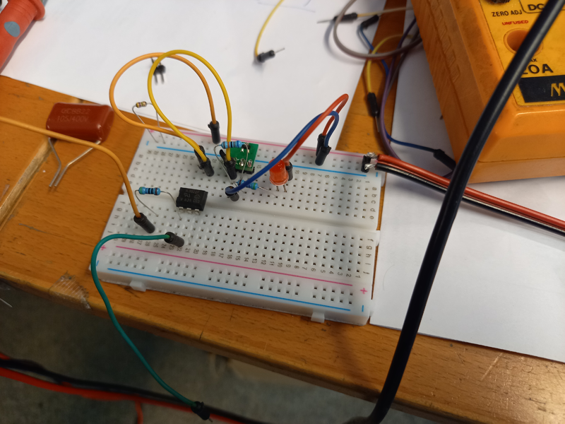
Figure 10: Propotype of the enery-saving circuitry to power the JA-151N on demand
Basically the circuit as shown in Figure 11 consists of an optocoupler with the input side (diode) soldered in parallel to one of the LEDs on the JA-163A PCB. The output of the optocoupler is tied to the Gate (input) of a FET (Field Effect Transistor) with the Source and Drain of the FET in the path of the power source for the JA-151N. With a condensator and resistor connected to that same gate the FET remains open even between flashes.
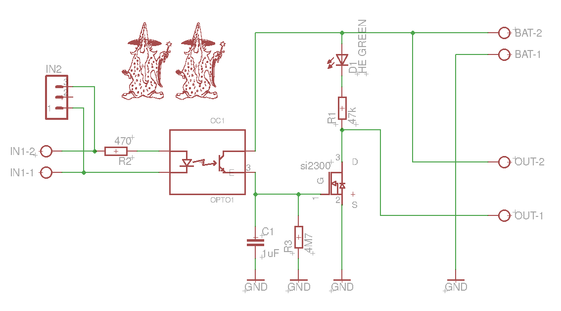
Figure 11: Schematics of the circuit to power the JA-151N on demand
With this circuit the power drain of the modification on the batteries is reduced to practically zero and it turned out to work very well. However, we did not really want to put a breadboard into our outdoor siren. Just as well because as we later found there may not have been enough space inside the JA-163A housing to fit in both the breadboard and the JA-151N.
In any case we decided it would be much neater to design a small PCB which BitWizard were kind enough to do for us:
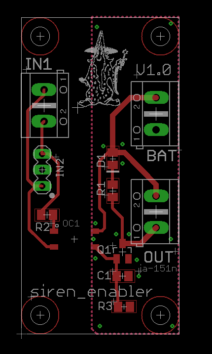
Figure 12: PCB layout
The PCB was ordered from China and then we had to wait for it to arrive, which did not take long. The components were then soldered and on the first test it turned out to work just as well as the prototype.
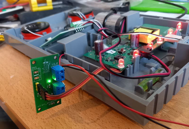
Figure 13: Circuit in action: The green LED indicates it is providing power to the JA-151N
With this circuit controlling the power supply to the JA-151N the batteries should last for many years, probably much longer than the battery of the JA-163A, so whenever that gets replaced we can simply also put in a fresh set of batteries for our additional PCB.
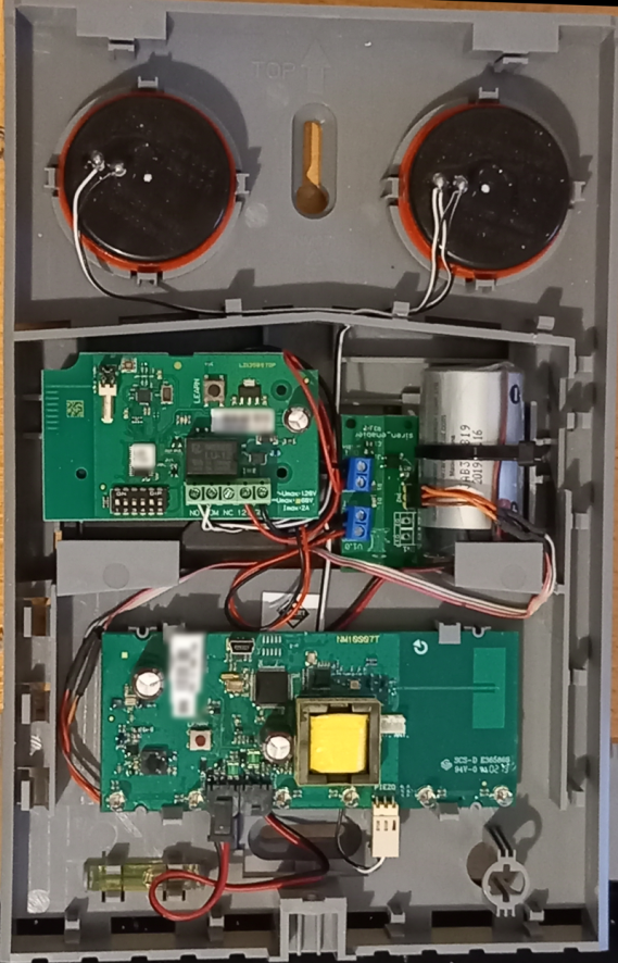
Figure 14: The JA-163A siren with the JA-151N (with our battery compartment underneath) and our Siren Enabled PCB
Perhaps someday Jablotron will update the fimrware of the JA-163A to allow activating the (audible) siren manually but until then we be using our own solution.
Have fun!
.

Related Posts

")